
Fire suppression pumps serve as the vital hydraulic heart of any life safety and fire protection system within buildings and critical facilities; any deficiency in operating pressure or volumetric flow results in the complete failure of automatic fire sprinkler networks, landing valves, and fire department connections. To provide a direct engineering answer to the question: what are the types of fire pumps? They are primarily classified from a hydraulic and mechanical perspective into centrifugal pumps and positive displacement pumps, and are categorized operationally by driver source into electric motor pumps, diesel engine pumps, and pressure maintenance jockey pumps. These systems are governed by rigorous engineering criteria and certification testing under National Fire Protection Association standards, Civil Defense mandates, the Saudi Building Code, and performance listings issued by accredited international testing laboratories.
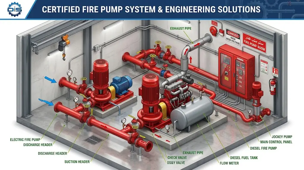
Table of Contents
- Classification of Fire Suppression Pumping Systems
- What Are the Types of Fire Pumps and Their Core Safety Role?
- Centrifugal Pumps and Horizontal/Vertical Split-Case Assemblies
- Vertical Turbine Pumps and End Suction Centrifugal Units
- Electric and Diesel Fire Pumps: Driver Source Redundancy
- The Role of the Jockey Pump in Maintaining Static Pressure
- Packaged Configurations (Standard Triad and Dual Hybrid Skids)
- Core Components and Layout of an Approved Pump Room
- Engineering Codes, NFPA 20 Standards, and Listing Mandates
- Practical Applications in High-Rise Towers, Warehouses, and Industrial Plants
- Technical Comparison Matrix of Operating Fire Pump Types
- Hydraulic Calculations, Volumetric Flow Rates, and Operating Pressures
- Inspection, Testing, and Periodic Maintenance Schedules
- Common Field Installation Errors and Mitigation Strategies
- Related Engineering and Fire Safety Technical Guides
- Frequently Asked Questions
- Engineering Summary and Professional Call to Action
Call Us |
Classification of Fire Suppression Pumping Systems
Certified stationary fire pumps governed by standard life safety codes are classified into the following core configurations:
- Horizontal Split-Case Pumps: The premier choice for major facilities owing to high mechanical efficiency, volumetric delivery exceeding five thousand gallons per minute, and simplified servicing without dismantling connected piping headers.
- End Suction Centrifugal Pumps: Applied across small to mid-sized occupancies with economical flow demands not exceeding one thousand five hundred gallons per minute, featuring a compact mounting footprint.
- Vertical Turbine Pumps: The sole engineering configuration approved when the water supply sits below the suction centerline, operating reliably under negative suction head conditions.
- Vertical In-Line Pumps: Tailored for compact mechanical rooms with flow capacities up to one thousand gallons per minute without requiring heavy concrete inertia bases.
- Diesel Engine Fire Pumps: Serving as the mandatory, fully independent mechanical backup line to ensure uninterrupted water delivery during total electrical blackouts.
- Electric Motor Fire Pumps: The primary daily duty driver delivering immediate operational response when energized by dedicated power feeders.
- Pressure Maintenance Jockey Pumps: Multi-stage centrifugal units rated at one to ten percent of total system flow, maintaining static network pressure and preventing false starts of primary drivers.
What Are the Types of Fire Pumps and Their Core Safety Role?
In technical terms, a fire pump is a specialized hydraulic machine engineered to elevate fluid velocity and dynamic head pressure to satisfy the hydraulic demands of suppression systems during life-threatening fire events. In an engineering context, answering what are the types of fire pumps requires a comprehensive understanding of structural casing design and hydraulic suction parameters, ensuring exact alignment with reservoir levels and site layout criteria to satisfy statutory industrial security mandates.
Fire protection pumps operate primarily on centrifugal principles, where fluid enters axially through the impeller eye and is accelerated radially outward by centrifugal force. The fluid velocity generated across the impeller blades transforms into usable static head pressure through the widening passages of the casing volute.
The defining standard governing these units is the characteristic performance curve: the pump must generate between one hundred and one percent and one hundred and forty percent of rated pressure at zero flow (shutoff churn), deliver one hundred percent rated flow at rated pressure, and produce at least one hundred and fifty percent of rated capacity at no less than sixty-five percent of its rated pressure.
Centrifugal Pumps and Horizontal/Vertical Split-Case Assemblies
Horizontal split-case pumps represent the foundational standard for fire suppression within heavy industrial plants and mega complexes, characterized by an axial volute casing split horizontally along the drive shaft into distinct upper and lower assemblies.
This geometry allows maintenance technicians to inspect and overhaul internal shafts, impellers, wear rings, and bearings by removing the upper casing cover without disturbing suction and discharge headers or realigning heavy driver couplings. Built with a double-suction impeller, water enters simultaneously from opposing sides to balance hydraulic axial thrust mechanically. This configuration reduces stress on radial and thrust bearings while supporting robust delivery rates from two hundred and fifty to over five thousand gallons per minute at pressures reaching three hundred pounds per square inch.
Conversely, vertical split-case configurations deliver identical hydraulic performance while reducing horizontal floor requirements by up to forty percent through vertical motor mounting, provided dynamic balancing is maintained to prevent shaft deflection during continuous operation.
| Engineering Parameter | Horizontal Split-Case Performance Specifications |
|---|---|
| Typical Flow Range | From 250 to over 5,000 Gallons Per Minute (GPM) |
| Hydraulic Pressure Range | From 40 to 300 Pounds Per Square Inch (PSI) |
| Impeller Hydraulic Geometry | Double-suction design eliminating bearing axial thrust loads |
| Primary Maintenance Advantage | Servicing rotating elements without disconnecting suction/discharge piping |
| Spatial and Structural Constraints | Demands expansive pump room footprints and substantial reinforced concrete inertia pads |
Vertical Turbine Pumps and End Suction Centrifugal Units
Site grading and fluid levels necessitate the deployment of vertical turbine pumps whenever raw water supplies create a negative suction head where conventional self-priming is unachievable.
Life safety standards mandate vertical turbine pumps when drawing from deep sub-surface reservoirs, wells, or open sumps where operating water levels fall below the pump intake centerline. Centrifugal pumps requiring manual or artificial priming are strictly prohibited in fire service. Vertical turbines feature a surface-mounted driver connected via a vertical line shaft to multi-stage submerged bowls and impellers terminating in a bottom suction strainer, keeping working elements constantly submerged under positive hydrostatic pressure to prevent air-binding and cavitation.
Conversely, end suction pumps take water in axially through the front suction flange and discharge it vertically upward. They offer an economical solution for commercial offices and light manufacturing facilities with capacities ranging from one hundred to one thousand five hundred gallons per minute. While offering back pull-out convenience, their single-suction overhung impeller generates uncompensated axial thrust that limits their deployment in severe, high-volume industrial systems.
Electric and Diesel Fire Pumps: Driver Source Redundancy
Safe engineering designs rely on redundant driver sources to guarantee steady water delivery during severe emergencies when municipal electrical grids are compromised.
Electric units utilize three-phase squirrel-cage induction motors, providing instantaneous response without warm-up delays. Installation standards mandate supplying electric fire pump controllers via dedicated two-hour fire-rated feeders connected ahead of the main building disconnect, or incorporating an Automatic Transfer Switch (ATS) linked to an emergency standby generator sized to support full locked rotor current.
Conversely, diesel engine fire pumps provide an independent mechanical safeguard operating entirely isolated from external power grids. These engines feature direct fuel injection and cooling systems utilizing liquid heat exchangers or engine-driven radiators. Standards dictate that every diesel driver must include dual independent starting battery banks with separate automatic chargers and redundant cranking contactors, ensuring instantaneous starting on pressure drops even if one battery bank fails completely.
Call Us |
The Role of the Jockey Pump in Maintaining Static Pressure
The jockey pump serves as a pressure-balancing device, engineered specifically to shield the primary pumps from mechanical wear and frequent electrical cycling.
Wet-pipe fire suppression networks are charged with pressurized water at pressures up to one hundred and fifty pounds per square inch, naturally experiencing minor pressure drops from ambient temperature changes or small valve weepage. The jockey pump—typically a vertical multi-stage centrifugal unit—replenishes these losses at modest flow rates between one and ten percent of total system demand (usually five to thirty-five gallons per minute), operating at a rated discharge pressure five to ten pounds per square inch above the main pump start threshold.
Routine cycling of the jockey pump prevents false starts of electric and diesel drivers. Under Civil Defense mandates and international codes, main fire pumps do not shut down automatically upon pressure restoration and require manual intervention to prevent controller and motor damage. Sizing the jockey pressure switch to start on minor drops and stop automatically when pressure is restored ensures stable system readiness.
Packaged Configurations (Standard Triad and Dual Hybrid Skids)
High-risk facilities require skid-mounted packaged fire pumping units engineered to deliver high operational redundancy, including the following configurations:
- Standard Triad Package: Comprises a primary electric motor pump, a secondary diesel engine pump providing one hundred percent standby capacity, and a pressure-maintenance jockey pump. This represents the mandatory configuration under Building Codes and Civil Defense regulations for high-rise buildings, large logistics warehouses, and medical centers.
- Dual Hybrid Configuration (Electric with Jockey): Permitted solely in low to moderate hazard facilities where two independent, fully verified utility power services are routed to an approved transfer switch.
- Dual Industrial Configuration (Diesel with Jockey): Deployed across remote mining concessions and open petrochemical processing yards lacking grid connections, where the diesel driver serves as the primary operational unit.
- Deluge and Water Spray Skids: Dedicated systems protecting oil-filled power transformers and gas terminals, utilizing fast-opening hydraulic deluge valves to flood fully open spray nozzles across designated hazards in seconds.
Core Components and Layout of an Approved Pump Room
An approved fire pump enclosure requires precision engineering extending beyond the pump casings to incorporate control panels, valves, and monitoring instrumentation:
- Automated Control Panels: The digital brains of the installation, which must be certified and listed by accredited laboratories, designed to withstand high short-circuit currents while monitoring pressure transducers, operational fault logs, and phase reversal indicators.
- Suction Header Assembly: Life safety standards strictly prohibit throttling valves on suction lines. Outside Screw and Yoke (OS&Y) rising stem gate valves with supervisory tamper switches are required to provide clear visual verification of an open waterway, alongside eccentric reducers installed flat-side-up to eliminate air pockets.
- Discharge Header Assembly: Features a concentric increaser, followed by a spring-loaded non-slam check valve to suppress water hammer, and an indicating butterfly control valve transmitting supervisory signals to the central fire alarm panel.
- Casing Relief Valve: Sized for electric pumps to release controlled amounts of cooling water during zero-flow shutoff conditions to prevent thermal buildup inside the casing.
- Main Pressure Relief Valve: Installed on the discharge side of diesel engine fire pumps to prevent over-pressurization caused by engine overspeed conditions.
- Dedicated Diesel Fuel Day Tank: Mounted adjacent to the engine with a dedicated gravity feed elevation, enclosed within a containment berm to prevent fuel spread in the event of tank rupture.
Engineering Codes, NFPA 20 Standards, and Listing Mandates
The design and procurement of fire suppression pumps are governed by integrated regulatory frameworks that guarantee emergency performance:
- NFPA 20 Stationary Fire Pump Standard: The core international standard governing suction and discharge velocities—capping fluid speeds at fifteen feet per second on suction and twenty feet per second on discharge—while specifying pump curve criteria.
- NFPA 25 Inspection, Testing, and Maintenance Standard: The regulatory benchmark establishing mandatory periodic inspection, testing, and maintenance routines for all water-based fire networks.
- UL and FM Listing Certifications: Third-party listings validating that pumps, drivers, and controllers comply with structural, electrical, and mechanical safety standards under severe operating conditions.
- Saudi Building Code (SBC 801) and Civil Defense Requirements: Mandating that all mechanical designs be prepared by accredited engineering bureaus, requiring secondary emergency driver backups and electronic monitoring of all control valves.
Practical Applications in High-Rise Towers, Warehouses, and Industrial Plants
Hydraulic parameters vary significantly depending on structural height and storage hazard profiles:
- High-Rise Commercial and Residential Towers: Overcoming hydrostatic head losses (roughly 0.433 PSI per vertical foot) requires partitioning buildings into distinct vertical pressure zones using intermediate booster pumps or multi-stage multi-outlet pumps to deliver balanced pressures without damaging lower-tier pipework.
- High-Piled Storage and Logistics Warehouses: Sized to supply Early Suppression Fast Response (ESFR) sprinkler heads that discharge high-velocity, large-droplet water streams to penetrate intense fire plumes, typically requiring split-case pumps rated between two thousand and five thousand gallons per minute.
- Petrochemical Refineries and Tank Farms: Severe hazard occupancies requiring high-horsepower diesel units and vertical turbine pumps drawing from seawater canals, fabricated from corrosion-resistant alloys such as nickel-aluminum bronze and duplex stainless steel.
Technical Comparison Matrix of Operating Fire Pump Types
The following engineering matrix outlines technical specifications to address what are the types of fire pumps and their operational applications:
| Pump Type | Rated Flow (GPM) | Pressure Range (PSI) | Approved Driver Source | Primary Advantages | Engineering Limitations | Common Applications |
|---|---|---|---|---|---|---|
| Horizontal Split-Case | 250 to over 5,000 | 40 to 300 | Electric Motor / Diesel Engine | High hydraulic efficiency, double-suction impeller, simplified servicing | Requires expansive floor area and precise alignment on inertia bases | Mega malls, industrial facilities, hospitals |
| End Suction Centrifugal | 100 to 1,500 | 50 to 200 | Electric Motor / Diesel Engine | Cost-effective installation, compact dimensions for restricted spaces | Axial loads on overhung impeller, limited maximum flow rates | Commercial offices, schools, retail stores |
| Vertical Turbine | 250 to 4,500 | 50 to 350 | Vertical Electric / Right-Angle Diesel | Draws from below-ground water sources without priming mechanisms | Higher equipment cost; requires crane access to service line shafts | Buried tanks, wells, marine docks, lakes |
| Vertical In-Line | 50 to 1,000 | 40 to 160 | Dedicated Electric Motor | Installs directly in pipe headers, requires no concrete pads | Difficult component access requiring driver removal, capacity caps | Hotels, compact urban pump rooms |
| Jockey Pump | 5 to 50 | 5 to 10 PSI above main | Three-Phase Electric Motor | Low power draw, fast response, maintains system static pressure | Provides zero fire suppression flow, handles minor leaks only | All mandatory stationary fire pump rooms |
Hydraulic Calculations, Volumetric Flow Rates, and Operating Pressures
System reliability relies on precise hydraulic modeling using the Hazen-Williams method to calculate three main parameters:
1. Calculating Rated Volumetric Demand Flow
Calculated by multiplying the most hydraulically demanding floor area by the required design discharge density, and adding the hose stream allowance mandated by the applicable occupancy code.
2. Calculating Net Total Dynamic Head (TDH)
The net pressure generated by the pump equals the required residual pressure at the most remote sprinkler or standpipe valve, plus the pressure needed to overcome static elevation rise and friction losses through pipes, fittings, and control valves, minus the positive suction head provided by the supply tank.
3. Calculating Driver Brake Horsepower (BHP)
Driver brake horsepower is calculated from the rated flow, total dynamic head, water specific gravity, and the hydraulic efficiency of the pump. The motor or engine must be sized to cover the peak horsepower point on the performance curve to prevent overloading at one hundred and fifty percent flow.
Inspection, Testing, and Periodic Maintenance Schedules
Periodic testing schedules under NFPA 25 and local regulations are essential to verify ongoing system readiness:
- Weekly Visual Inspections: Checking suction and discharge pressure gauges, verifying that isolation valves remain locked open, inspecting fuel levels, oil, and coolant on diesel drivers, and conducting a 30-minute no-flow churn test on diesel engines (10 minutes monthly on electric sets).
- Monthly and Quarterly Inspections: Testing automated pressure switches via test valves, inspecting packing seals for proper cooling leakage, and exercising emergency transfer switches (ATS).
- Annual Full-Flow Test: Discharging water through a test header or flow meter to measure performance at zero flow (churn), 100% rated flow, and 150% peak flow, confirming pump curves remain within 5% of original factory benchmarks.
Common Field Installation Errors and Mitigation Strategies
Installation mistakes can compromise pump performance during an emergency. Key errors and their solutions include:
- Concentric Reducers on Suction Lines: Traps air pockets at the top of the pipe, causing cavitation and impeller pitting. Solution: Install eccentric reducers with the flat side oriented upward.
- Elbows Flanged Directly to Suction Inlets: Causes uneven flow distribution across double-suction impellers, leading to bearing wear. Solution: Provide a straight pipe run of at least ten pipe diameters upstream of the suction flange.
- Omitting Casing Relief Valves: Allows water to boil inside the casing during churn operation, damaging packing and internal seals. Solution: Install an automatic thermal relief valve discharging to an open drain.
- Butterfly Valves on Suction Headers: Creates turbulent inflow and introduces water hammer risks from rapid closure. Solution: Use OS&Y rising stem gate valves equipped with tamper switches on all suction headers.
Related Engineering and Fire Safety Technical Guides
- Automatic Fire Sprinkler System Design Guidelines
- Pump Room Ventilation, Drainage, and Construction Standards
- Hydraulic Pipe Sizing Methodologies Using Hazen-Williams Formulas
- UL/FM Fire Pump Controller Specifications and Requirements
- NFPA 25 Water-Based System Maintenance and Licensing Protocols
- Technical Guide to OS&Y Gate Valves, Non-Return, and Deluge Assemblies
Frequently Asked Questions
What are the types of fire pumps?
Certified stationary fire pumps include centrifugal horizontal split-case, end suction, vertical turbine, and vertical in-line units, alongside positive displacement pumps for foam systems. They operate via electric motors or diesel engines, supported by a pressure-maintenance jockey pump.
How does a consulting engineer determine the best pump for a project?
Selection is based on water source elevation, flow rates, and hydraulic calculations: vertical turbines are specified for sub-grade reservoirs and wells, horizontal split-case pumps for large industrial facilities, and end suction units for smaller commercial buildings with positive suction.
What is the maximum allowable churn pressure at zero flow?
Standards require shutoff churn pressure to remain between 101% and 140% of rated design pressure, preventing pipe rupture when the pump starts automatically before valves or sprinklers open.
Why are end suction pumps prohibited under negative suction conditions?
End suction pumps cannot self-prime. Operating with water supplies below the impeller creates air binding and cavitation, stopping water delivery entirely. Vertical turbine pumps with submerged impellers are required for negative lift applications.
What is the required start-up time for a standby diesel engine?
A standby diesel fire pump must start, crank, and reach full rated operating speed within 20 seconds of receiving a low-pressure signal or utility power failure.
What is the difference between OS&Y gate valves and supervisory butterfly valves?
OS&Y gate valves use a threaded stem that rises as the valve opens, providing visual confirmation of an unobstructed waterway, making them mandatory on suction headers. Butterfly valves utilize an internal rotating disc with integral monitoring switches, permitted on discharge and test lines to save space.
Call Us |
Engineering Summary and Professional Call to Action
Designing fire suppression systems requires engineering precision that meets Saudi Building Code (SBC 801), Civil Defense, and NFPA standards. Properly identifying what are the types of fire pumps required for a facility depends on certified hydraulic modeling to prevent design errors in suction lines and pressure distribution.
Engineering consultants, MEP contractors, and facility managers should specify certified equipment to ensure life safety compliance and system reliability during emergencies.
To design, supply, or audit fire pumps and hydraulic calculations for your facility, contact Thermoshield Safety & Contracting Company to evaluate your project requirements.