

Purchasing a fire pump that strictly matches a manufacturer catalogue does not necessarily guarantee that the firefighting system will operate reliably during an emergency. The pump is merely one component of an integrated hydraulic network; any flaw in its physical positioning, suction and discharge piping, or power supply will degrade performance below design thresholds, even if the unit itself is fully compliant with the NFPA 20 standard. This reality makes NFPA 20 fire pump specifications a precise engineering subject requiring thorough technical expertise rather than simply selecting a model from a catalogue.
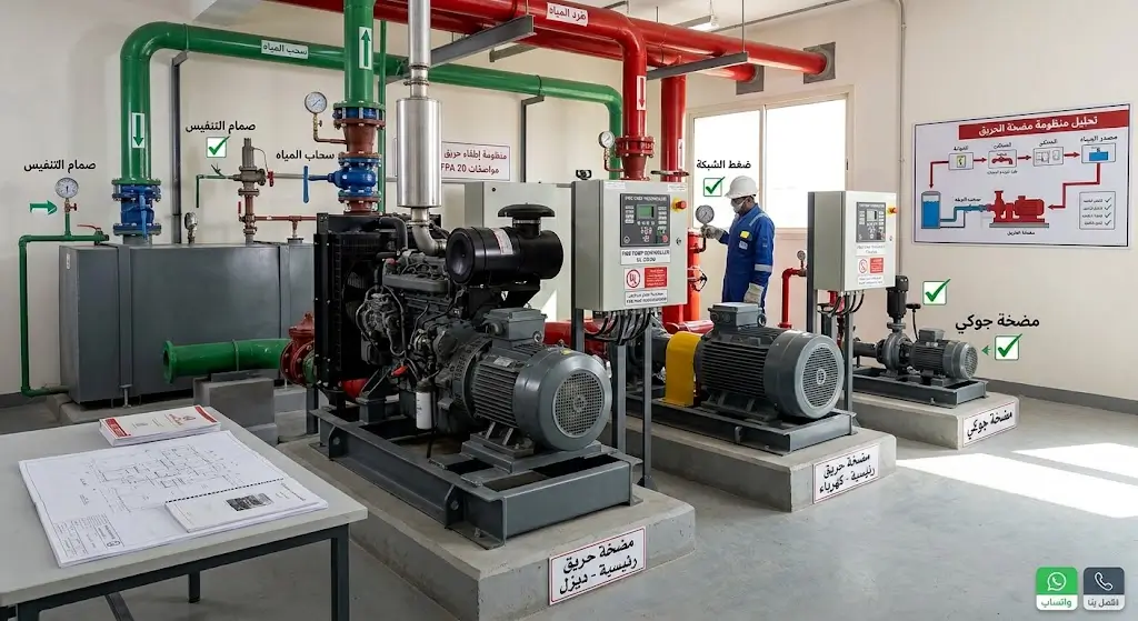
Table of Contents
- What is the Relationship Between Fire Pumps and the Firefighting Network?
- NFPA 20 Fire Pump Specifications and Approved Types
- How is the Proper Fire Pump Selected?
- Location and Design of the Fire Pump Room
- Fire Pump Installation and Piping Connection Steps
- Testing Fire Pumps Post-Installation (Acceptance Testing)
- Common Errors During Fire Pump System Execution
- The Difference Between Installation and Maintenance (NFPA 20 vs. NFPA 25)
- When Does a Facility Require a Specialized Engineering Firm?
- Factors Influencing the Cost of Fire Pump Implementation
- Documents and Engineering Blueprints Required Before Execution
- Frequently Asked Questions About NFPA 20 Fire Pump Specifications
- Conclusion
📞 Call Us |
What is the Relationship Between Fire Pumps and the Firefighting Network?
A fire pump does not operate in isolation. Its functional duty is to elevate the pressure of incoming water from the supply source—whether an underground storage tank, suction reservoir, or municipal water main—to the precise pressure and flow rate demanded by the internal firefighting distribution network, whether feeding automatic fire sprinklers, fire hose cabinets, or combined standpipe systems.
A complete fire pump set typically comprises:
- The Primary Fire Pump: Delivers the primary design water flow and head pressure required to activate and sustain fire suppression systems.
- The Jockey Pump (Pressure Maintenance Pump): A small auxiliary pump that maintains constant hydrostatic pressure within the network, compensating for minor seepage or thermal variations without cycling the primary fire pump unnecessarily during non-emergency conditions.
- The Diesel Engine Fire Pump: Serves as an autonomous backup unit during total power failure, or acts as the primary driver in facilities lacking an adequately dependable utility grid.
- The Electric Motor Fire Pump: The standard driver choice when supported by a highly reliable utility service, often backed by an on-site emergency generator and automatic transfer switch (ATS).
- The Fire Pump Controller: The listed control apparatus dedicated to monitoring electrical and pressure parameters, automatically starting drivers upon sensing line pressure drops, and logging alarm and operational events.
This functional division dictates that designing an effective life safety infrastructure begins with assessing the comprehensive piping layout to satisfy Safety and security requirements, rather than selecting a standalone pump independently.
NFPA 20 Fire Pump Specifications and Approved Types
The NFPA 20 standard strictly regulates the specific pump types permissible for fire suppression duty, prohibiting standard commercial water pumps. Fire pumps must be formally listed by recognized third-party laboratories (such as UL or FM Global) and factory-tested against rigorous safety performance standards. Common configurations governed by NFPA 20 fire pump specifications include:
- Horizontal Split Case (HSC) Centrifugal Pumps: Widely specified for medium-to-large commercial and industrial developments where floor space is ample and elevated flow capacities are required.
- End Suction Pumps: Feature a compact footprint, making them ideal for facilities and building footprints with tight pump room dimensions.
- Vertical Turbine Pumps: Specified when the water supply originates from deep wells, below-ground reservoirs, or submerged wet pits where flooded suction cannot be maintained.
Regarding power drivers, the standard authorizes listed electric motors, diesel engines, and in rare industrial applications, steam turbines. Driver selection hinges primarily on the reliability of the site power infrastructure—facilities dependent on a single grid transformer without an auxiliary standby supply invariably require a diesel-driven pump as a mandatory contingency.
How is the Proper Fire Pump Selected?
Selecting an optimal pump begins with precision hydraulic calculations across the suppression piping, rather than evaluating commercial pricing models. Key parameters governed by NFPA 20 fire pump specifications include:
- Required Flow Rate (GPM): Determined based on hazard classification, sprinkler density criteria, and simultaneous hose stream allowances.
- Total Dynamic Head / Pressure (PSI): Calculated from the hydraulically most remote nozzle, total static elevation, and cumulative friction losses across fittings, valves, and distribution pipework.
- Available Suction Pressure (NPSHa): The pump must maintain sufficient net positive suction head to prevent damaging cavitation phenomena that degrade impellers and compromise hydraulic output.
- System Occupancy Profile: Sprinkler-only networks impose distinct demand curves compared to high-demand class I/III wet standpipes or deluge systems.
These calculations dictate motor horsepower, pump sizing, and header diameters. Procuring an arbitrary pump capacity prior to completing hydraulic modeling is a severe design mistake that leads to operational failures during fire incidents.
📞 Call Us |
Location and Design of the Fire Pump Room
The fire pump room is a mission-critical enclosure reserved exclusively for life safety apparatus. Key architectural mandates set forth by NFPA 20 fire pump specifications include:
- Direct exterior egress or access via an enclosed 2-hour fire-rated passageway to allow unobstructed entry during an active fire event.
- Passive fire separation constructed from non-combustible materials, maintaining at least a 2-hour fire-resistance rating in high-rise and high-hazard occupancies.
- Controlled ambient temperature maintained at or above 4°C (40°F) for electric sets, or 21°C (70°F) for direct diesel engine rooms lacking block heaters.
- Location restrictions prohibiting placement beneath kitchens, sanitary wet areas, or industrial tanks prone to liquid leakages.
- Adequate ventilation provisions engineered to satisfy diesel combustion air requirements and exhaust dissipation safely outside the facility.
Within the Kingdom of Saudi Arabia, these room designs require prior verification from Civil Defense to satisfy Prevention and protection requirements, as structural alterations after concrete pouring necessitate substantial rework.
Fire Pump Installation and Piping Connection Steps
Suction and Discharge Piping
The suction pipe conveys water from the source to the pump impeller, while the discharge header channels pressurized water into the fire suppression grid. Design integrity on these lines directly governs pump longevity and hydraulic output:
- Sizing pipe diameters sufficiently to prevent excessive friction loss and velocity issues (velocity restricted below 15 ft/sec at 150% rated flow on suction lines).
- Maintaining flooded suction geometry whenever feasible to prevent air infiltration and priming failure.
- Eliminating air pockets along the suction run by utilizing eccentric reducers (flat-on-top) rather than concentric reducers to suppress vortexing and turbulence.
Valves and the Fire Pump Controller
The pump manifold incorporates a dedicated array of listed valves specified under NFPA 20 fire pump specifications:
- Check Valve: Installed on the discharge line to prevent water backflow, protect the casing from hydraulic surge, and maintain static header pressure.
- Isolation Valves (OS&Y Gate Valves / Indicating Butterfly Valves): Allow equipment isolation during maintenance without draining the entire distribution grid. All valves must be electrically supervised for open position.
- Test Header: A listed exterior manifold equipped with independent 2.5-inch hose valves to permit safe periodic flow testing without discharging into the facility.
The fire pump controller monitors pressure transducers and automates starting sequences upon detecting threshold drops. Controllers must carry dedicated fire service listings and be installed strictly according to factory documentation and NFPA 20 wiring protocols.
Electrical Interconnections and Power Supplies
Electric units require dedicated, fire-protected power conductors routed ahead of the main facility disconnect. Where grid reliability is compromised, an automatic transfer switch (ATS) coupled to a listed emergency generator is mandatory.
Diesel drivers require a dedicated fuel day-tank sized for at least 8 hours of continuous full-load operation (1 gallon per horsepower plus 10% safety margin), supported by dual battery racks and automatic dual-rate chargers to ensure instantaneous cranking power.
Testing Fire Pumps Post-Installation (Acceptance Testing)
No fire pump installation is deemed complete without an official on-site field acceptance test validating that the physical installation performs along its certified factory performance curve per NFPA 20 fire pump specifications. The test records three primary operating points:
- Shutoff / Churn Pressure (0% Flow): All discharge outlets remain closed. The measured churn pressure must not exceed 140% of rated head pressure for centrifugal sets.
- Rated Capacity (100% Flow): The pump must produce at least 100% of its rated nameplate pressure while delivering 100% of rated flow capacity.
- Peak Load (150% Flow): At 150% of rated flow capacity, the pump must sustain a discharge pressure of not less than 65% of its rated nameplate pressure.
Achieving these three benchmark points confirms hydraulic integrity and serves as an indispensable prerequisite for securing final تراخيص السلامة الرسمية occupancy approvals.
Common Errors During Fire Pump System Execution
Execution flaws can critically compromise system dependability during emergencies, including:
- Undersizing suction or discharge pipe diameters, causing extreme friction losses that starve the sprinkler network.
- Omitting the jockey pump or miscalibrating its pressure switch, forcing the primary unit to start repeatedly on minor leaks and causing early motor burnout.
- Installing unlisted commercial plumbing valves and generic controllers in place of dedicated fire-service hardware.
- Utilizing the pump room as a storage space, a violation resulting in immediate inspection failure when applying for Safety licenses certification.
- Undersizing diesel fuel storage capacity relative to the statutory runtime demanded by local code.
- Neglecting suction head analysis (NPSH), triggering destructive cavitation during operational runs.
The Difference Between Installation and Maintenance (NFPA 20 vs. NFPA 25)
System installation is a one-time construction phase governed strictly by NFPA 20 fire pump specifications, concluding with formal acceptance testing. Conversely, continuous operational inspection, testing, and servicing fall under NFPA 25 (Standard for the Inspection, Testing, and Maintenance of Water-Based Fire Protection Systems).
NFPA 25 requires weekly operational churn testing for diesel drivers, monthly testing for electric sets, annual full-flow testing with calibrated pitot equipment, and periodic mechanical overhauls to preserve statutory readiness during Renewal of technical licenses renewal periods.
When Does a Facility Require a Specialized Engineering Firm?
Certain critical engineering decisions must be executed exclusively by licensed life safety practitioners, such as:
- Executing computer-generated hydraulic calculations to establish precise pump flow (GPM) and head (PSI).
- Determining driver type and secondary emergency power configurations based on utility grid dependability.
- Coordinating pump manifold layouts with wider Security and safety plans, alarm systems, and automatic suppression zones.
- Preparing shop drawings, equipment submittals, and compliance reports for Civil Defense approval.
- Supervising on-site acceptance testing and providing certified engineering test documentation.
Thermoshield Safety and Contracting Company delivers comprehensive engineering solutions encompassing fire pump supply, hydraulic layout design, risk assessment studies, and Civil Defense approvals through to turnkey commissioning.
Factors Influencing the Cost of Fire Pump Implementation
Total investment costs for a fire pump installation depend on several interrelated engineering factors:
- Pump and Driver Architecture: A complete triad set (electric + diesel + jockey) represents a different capital investment compared to standalone electric pump configurations.
- Hydraulic Sizing Requirements: Required flow volume (GPM) and total dynamic pressure (PSI).
- Listing and Certification Standards: UL-Listed and FM-Approved packages represent rigorous manufacturing standards reflected in equipment costs.
- Associated Mechanical and Electrical Infrastructure: High-pressure piping, supervised OS&Y valves, ATS panels, fuel loops, and room ventilation systems.
Documents and Engineering Blueprints Required Before Execution
Prior to breaking ground on pump room assembly, the following technical documentation must be reviewed and stamped:
- Hydraulic calculations calculated per NFPA 20 and SBC standards.
- Detailed shop drawings detailing pump orientation, suction/discharge routing, and valve stations.
- Civil Defense preliminary approvals and stamped safety drawings.
- Water supply capacity assessments certifying adequate duration for emergency flow.
Frequently Asked Questions
What is the primary role of a jockey pump in a fire pump set?
The jockey pump maintains constant hydrostatic pressure within the distribution network, compensating for minute leakages without starting the primary pump unnecessarily.
Can a facility omit the diesel fire pump if utility electric power is available?
Omission is permissible only if the electric supply is backed by an approved independent secondary utility substation or an on-site emergency generator with a listed ATS. Otherwise, an autonomous diesel driver is mandatory under NFPA 20.
What is the key difference between acceptance testing and periodic maintenance?
Acceptance testing is an initial commissioning protocol under NFPA 20 verifying equipment performance against design curves. Periodic maintenance is an ongoing operational regime governed by NFPA 25 across the building lifecycle.
Why do Civil Defense authorities reject certain fire pump room designs?
Rejections stem from insufficient maintenance clearances, substandard ventilation, using the pump enclosure for storage, or placement underneath wet architectural zones without moisture protection.
Does NFPA 20 limit installations to only one pump type?
No, the standard governs various centrifugal types—including horizontal split case, end suction, and vertical turbine units—tailored to specific water supply parameters and architectural layouts.
📞 Call Us |
Conclusion
Installing a fire pump system is not merely about procuring equipment from a catalogue; it requires rigorous hydraulic design, listed component selection, and field acceptance testing to verify real-world operational reliability. The gap between a catalog-listed pump and an emergency-ready suppression network is bridged only through rigorous engineering and strict compliance with NFPA 20 fire pump specifications from day one.
To design, install, or audit your facility fire pump system, contact Thermoshield Safety and Contracting Company to review your project criteria and establish required technical scopes prior to execution.