

Precise hydraulic calculations form the foundational engineering pillar determining the operational reliability of fire suppression systems and their ability to control fires and protect lives and assets. Deficiencies in flow and pressure calculations not only trigger engineering rejection by safety and Civil Defense authorities but also lead to the catastrophic failure of automatic sprinkler networks and standpipe hose stations during actual emergency incidents. To provide a direct engineering answer to the question: how are fire pumps calculated? It requires a disciplined mathematical and mechanical methodology anchored on two interdependent axes: determining the total design volumetric flow rate in gallons per minute (GPM), and computing the net total dynamic head (TDH) of the pump in pounds per square inch (PSI) or bar. These computations adhere strictly to National Fire Protection Association standards and the Saudi Building Code, ensuring full compliance with performance curves certified by international testing laboratories.
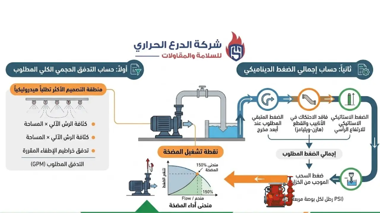
Table of Contents
- Definitive Answer: How Are Fire Pumps Calculated Technically?
- Engineering Methodology: Calculation Steps and System Requirements
- Calculating Required Volumetric Flow Rates for Sprinklers and Standpipes
- Computing Operating Pressure and Net Total Dynamic Head (TDH)
- Hazen-Williams Friction Loss Equations in Pipes and Fittings
- Vertical Elevation and Gravity Pressure in High-Rise Buildings
- Standardized Engineering Criteria in Pump Selection
- Fire Pump Sizing Classifications by Facility Profile
- Hydraulic Pump Types and Their Operating Applications
- Pump Performance Curve Analysis and Standard Operating Points
- International Listings and Civil Defense Acceptance Criteria
- Common Errors in Hydraulic Calculations and How to Avoid Them
- Hydraulic Modeling Software and Commissioning Testing Protocols
- Related Engineering and Technical Guides
- Official Standards and Regulatory Authorities
- Frequently Asked Questions
- Engineering Conclusion and Professional Call to Action
Call Us |
Definitive Answer: How Are Fire Pumps Calculated Technically?
Fire pump calculations are performed by establishing two core parameters: the total required flow rate obtained by combining the water demand of the most hydraulically demanding sprinkler zone with hose stream allowances, and the total dynamic head computed by summing residual discharge pressures, static elevation differences, and friction losses using the Hazen-Williams formula, minus the minimum available suction supply head.
- Total Flow Rate Computation: Combines remote design area sprinkler demand and mandatory hose stream allowances.
- Total Dynamic Head Computation: Incorporates remote discharge pressure, vertical static head differentials, and pipe friction losses, offset by positive suction tank pressure.
- Performance Curve Alignment: Plots the design point onto an approved pump curve, verifying that delivery capacity reaches at least 150% of rated flow at no less than 65% of rated pressure, backed by jockey pump pressure maintenance.
Engineering Methodology: Calculation Steps and System Requirements
Answering how are fire pumps calculated relies on evaluating building occupancy classifications and hazard profiles defined within building codes, categorizing facilities into light, ordinary, and extra hazards to establish design densities and operating areas compliant with life safety standards.
| Engineering Stage | Technical & Procedural Action | Approved Standard Reference |
|---|---|---|
| Hazard Classification | Establish occupancy type, design density (GPM/sq.ft), and operating area (sq.ft). | Sprinkler and Fire Building Code Standards |
| Water Flow Computation | Multiply operating area by design density and add mandated hose stream demand. | Sprinkler and Standpipe Network Standards |
| Critical Path Identification | Identify the longest piping route reaching the most remote hydraulic node. | Hydraulic Analysis of Remote Areas |
| Hydraulic Friction Loss | Apply the Hazen-Williams equation to calculate pressure drops across pipes and fittings. | Stationary Pump and Sprinkler Standards |
| Static Elevation Head | Compute pressure generated by vertical height differences between pump centerline and remote heads. | Classical Hydraulics & Gravity Head Principles |
| Operating Point Selection | Plot total flow and net head to select a pump aligned with certified performance curves. | Stationary Fire Pump Installation Criteria |
Calculating Required Volumetric Flow Rates for Sprinklers and Standpipes
Total volumetric flow is calculated by summing sprinkler demands from the most hydraulically remote area with manual fire hose and cabinet allowances, aligned with hazard protection regulations.
Sprinkler network demand is determined by multiplying operating design area by required density:
- Operating Design Area: The hydraulic footprint demanding peak output, ranging from 1,500 sq.ft for light hazards up to 5,000 sq.ft for high-hazard storage warehouses.
- Design Density: Starting at 0.10 GPM/sq.ft for light hazards, scaling to 0.20 for ordinary hazards, and exceeding 0.30 – 0.60 GPM/sq.ft for high-density storage facilities.
Hose stream allowances are added based on hazard classification:
- Light Hazard: 100 GPM (typically maintained for a 30-minute duration).
- Ordinary Hazard: 250 GPM (maintained for 60 to 90 minutes).
- Extra Hazard: 500 GPM (maintained for 90 to 120 minutes).
In buildings equipped with wet standpipe systems, flow is calculated at 500 GPM for the most remote standpipe riser, plus 250 GPM for each additional riser, up to a maximum of 1,000 GPM for fully sprinklered buildings or 1,250 GPM for non-sprinklered structures.
Computing Operating Pressure and Net Total Dynamic Head (TDH)
Total Dynamic Head represents the mechanical energy added by the pump to deliver water at required pressures to the highest and most remote discharge point, adhering to safety compliance standards.
- Required Residual Pressure: Minimum pressure at the remote sprinkler head, ranging from 7 to 12 PSI for standard heads up to 75 PSI for ESFR storage heads, while standpipe risers demand at least 100 PSI at the remote hose valve outlet.
- Static Elevation Head: Pressure required to lift water vertically from the pump centerline to the highest system elevation.
- Friction Losses: Cumulative pressure drops resulting from fluid friction against pipe walls, fittings, and valves along the critical path.
- Net Suction Head: Positive hydrostatic pressure available at the pump suction flange from the water storage reservoir at low water level, subtracted from total pressure requirements.
Hazen-Williams Friction Loss Equations in Pipes and Fittings
The Hazen-Williams equation is the standardized hydraulic method for computing friction pressure drops in fire suppression piping, where losses vary directly with flow rate and inversely with pipe diameter and internal wall smoothness.
Friction coefficients are assigned based on pipe material and system environment:
| Pipe Material and Type | Standard Roughness Coefficient (C) | Applied System Environment |
|---|---|---|
| Black Steel (Uncompromised) | 120 | Standard wet pipe indoor suppression systems |
| Carbon Steel for Dry Systems | 100 | Dry pipe and open deluge water spray grids |
| Galvanized Steel | 120 | External fire protection networks exposed to weather |
| Treated Fire Suppression Plastic (CPVC) | 150 | Light hazard residential occupancy networks |
| Cement-Lined Ductile Iron | 140 | Underground main feeder and fire loop rings |
To account for fittings and valves, equivalent straight pipe lengths are added to actual network dimensions prior to calculating total friction loss:
| Nominal Pipe Size | Standard 90° Elbow | Long Radius 90° Elbow | OS&Y Gate Valve | Swing Check Valve |
|---|---|---|---|---|
| 2 Inches | 5 Feet | 3 Feet | 1 Foot | 11 Feet |
| 2.5 Inches | 6 Feet | 4 Feet | 1 Foot | 14 Feet |
| 3 Inches | 7 Feet | 5 Feet | 1 Foot | 16 Feet |
| 4 Inches | 10 Feet | 6 Feet | 2 Feet | 22 Feet |
| 6 Inches | 14 Feet | 9 Feet | 3 Feet | 32 Feet |
| 8 Inches | 18 Feet | 13 Feet | 4 Feet | 45 Feet |
Vertical Elevation and Gravity Pressure in High-Rise Buildings
Water columns exert a gravitational static head penalty equal to 0.433 PSI per vertical foot (or roughly 0.1 bar per vertical meter), demanding rigorous engineering to prevent lower floors from experiencing destructive static pressures exceeding piping component ratings, while maintaining compliance with Civil Defense licensing costs and technical mandates.
Engineering mitigation in high-rises requires partitioning systems into independent vertical pressure zones:
- UL/FM Pressure Reducing Valves: Installed to regulate lower floor pressures and maintain steady discharge thresholds at 100 PSI.
- Multi-Stage Multi-Outlet Pumps: Delivering varied discharge pressures across different building elevations from a single central pumping station without secondary low-level tanks.
- Series Booster Fire Pumps: Deploying intermediate booster pumps across dedicated mechanical floors to lift water sequentially for super-tall skyscrapers.
Call Us |
Standardized Engineering Criteria in Pump Selection
International standards, building codes, and fire regulations establish rigorous criteria governing pump stations:
- Hydraulic Velocity Limits: Fluid speeds must not exceed 15 ft/s on suction lines at 150% rated flow, and 20 ft/s on discharge headers to prevent cavitation and water hammer.
- Prohibition of Throttling Valves on Suction: Butterfly valves are banned on suction lines; OS&Y rising stem gate valves with supervisory tamper switches are mandatory to guarantee open waterway verification.
- Eccentric Reducers: Suction reducers must be installed flat-side-up to prevent air pocket formation and air-binding at the impeller.
- Power Source Redundancy: Building codes mandate dual independent power supplies, fulfilled via electric motor pumps backed by emergency generators with automatic transfer switches, or standard electric-diesel driver combinations.
Fire Pump Sizing Classifications by Facility Profile
Capacities, flow rates, and operating pressures vary depending on facility architecture, storage height, and hazard profile as detailed in our benchmark matrix:
| Facility Type and Occupancy | Estimated Area | Rated Flow (GPM) | Operating Pressure Range (PSI) | Recommended Pump Configuration |
|---|---|---|---|---|
| Residential Villas and Palaces | Up to 1,500 m² | 250 – 500 | 40 – 70 | End suction electric with pressure maintenance jockey |
| Residential & Commercial Offices | Up to 6,000 m² | 500 – 750 | 75 – 100 | End suction or split-case (electric and diesel) |
| Medium Hazard Warehouses | 3,000 – 10,000 m² | 750 – 1,000 | 90 – 130 | Horizontal split-case with electric & diesel drivers |
| High-Rise Towers & Hospitals | Multi-story high-rise | 1,000 – 1,500 | 130 – 220 | Horizontal split-case or vertical multi-stage |
| Mega Shopping Malls | Over 25,000 m² | 1,500 – 2,000 | 100 – 150 | Horizontal split-case standard E.D.J triad package |
| High-Piled Storage Facilities | High-rack vertical storage | 2,000 – 3,000 | 140 – 190 | Split-case pumps engineered for ESFR systems |
| Petrochemical Plants & Airports | Severe hazard critical plants | 3,000 – 5,000+ | 150 – 250 | Vertical turbine or heavy-duty split-case units |
Hydraulic Pump Types and Their Operating Applications
Sizing accuracy is tied to selecting the correct mechanical configuration aligned with site water sources, as detailed in our guide on what are the types of fire pumps:
- Horizontal Split-Case Pumps: Featuring an axially split volute and double-suction impeller that balances axial thrust mechanically, serving as the standard for major facilities with flows from 250 to over 5,000 GPM.
- End Suction Pumps: Taking water in axially and discharging vertically, providing an economical choice for residential and mid-sized commercial projects handling 100 to 1,500 GPM.
- Vertical Turbine Pumps: The mandatory engineering solution when operating water levels sit below the pump suction centerline, keeping internal hydraulic stages submerged to ensure positive suction.
- Pressure Maintenance Jockey Pumps: Multi-stage vertical centrifugal units operating at 1% to 10% of main pump flow to offset minor leakage and pressure drops without engaging primary pumps.
Pump Performance Curve Analysis and Standard Operating Points
Fire pumps are classified hydraulically by complying with three mandatory test operating points along their performance curve under safety standards:
- Shutoff / Churn Head (Zero Flow): When network outlets are completely closed, pump pressure must remain between 101% and 140% of rated design pressure to protect piping from over-pressurization.
- Rated Design Point (100% Flow): The primary operating point where the pump delivers 100% of rated flow capacity at 100% of rated head pressure.
- Peak Load Point (150% Flow): When flow reaches 150% of rated capacity, delivered head must not drop below 65% of rated pressure, ensuring effective suppression when extra sprinkler heads open.
International Listings and Civil Defense Acceptance Criteria
Obtaining listings from accredited international testing laboratories is the definitive benchmark confirming compliance with building codes and Civil Defense regulations, streamlining safety and prevention licensing without delays.
- Structural Integrity and Hydrostatic Testing: Verifying casing strength under hydrostatic pressures equal to twice maximum operating pressure for at least five continuous minutes without distortion or leakage.
- Continuous Overload Testing: Ensuring impeller cooling efficiency and structural durability while running at 150% of rated flow capacity.
- Certified Controller Assemblies: Ensuring electric and diesel pump controllers withstand high short-circuit currents while providing digital event logging and phase monitoring.
Common Errors in Hydraulic Calculations and How to Avoid Them
Calculation mistakes and field errors lead to commissioning failures or emergency pump malfunctions. Key errors and engineering solutions include:
- Omitting Secondary Fitting Losses: Calculating straight pipe runs while ignoring valve and fitting equivalent lengths drops actual network pressure. Solution: Incorporate exact equivalent lengths for every mechanical fitting per engineering tables.
- Assuming Full Tank Suction Pressures: Calculating suction assuming a completely full tank is a critical error since water levels drop during fires. Solution: Compute hydraulics based on tank dead storage bottom levels.
- Placing Elbows Directly on Suction Flanges: Induces turbulent inflow into double-suction impellers, damaging bearings and causing cavitation. Solution: Provide a straight pipe run equal to at least 10 pipe diameters upstream of suction intakes.
- Using End Suction Pumps on Negative Suction: Deploying centrifugal units above ground relying on suction lift is a code violation. Solution: Utilize submerged vertical turbine pumps exclusively for negative lifts.
Hydraulic Modeling Software and Commissioning Testing Protocols
Specialized engineering offices rely on certified hydraulic software to perform complex network analysis, friction loss calculations, and flow distribution modeling aligned with Hazen-Williams equations, supporting technical license renewals.
System sustainability requires adherence to NFPA 25 field commissioning and testing protocols:
- Annual Full-Flow Testing: Measuring pump performance at 0%, 100%, and 150% flow rates using test headers or certified meters, comparing results against original factory curves, rejecting pumps dropping over 5% in performance.
- Pressure Switch Calibration: Verifying sensitivity of automatic start signals for jockey and main pumps to ensure reliable sequencing.
- Internal Corrosion Mitigation: Performing water quality analysis, dosing corrosion inhibitors, and using treated piping to prevent tuberculation and friction loss increases.
Related Engineering and Technical Guides
- What Are the Types of Fire Pumps: Comprehensive Engineering Guide
- Civil Defense License Cost and Salamah Platform Fees Guide
- Automatic Fire Sprinkler System Design Under NFPA 13 Standards
- Fire Pump Room Ventilation, Drainage, and Construction Guidelines
- NFPA 25 Inspection, Testing, and Maintenance Compliance Protocols
- Technical Guide to OS&Y Gate Valves, Non-Return, and Deluge Assemblies
Official Standards and Regulatory Authorities
- National Fire Protection Association (NFPA): International standards governing stationary pump installation, sprinkler networks, standpipe systems, and water-based system maintenance.
- National Committee for the Saudi Building Code: General, mechanical, and fire building codes for structural installations.
- Saudi Standards, Metrology and Quality Organization (SASO): Energy efficiency regulations and centrifugal pump manufacturing specifications.
- General Directorate of Civil Defense in Saudi Arabia: Executive regulations and preventive safety criteria for pump rooms and licensing.
Frequently Asked Questions
How are fire pumps calculated directly?
Fire pumps are calculated by determining total volumetric flow (GPM)—combining remote sprinkler demand and hose stream allowances—and computing total dynamic head (TDH) by summing remote residual pressures, static elevation head, and Hazen-Williams pipe friction losses, minus minimum available suction supply head.
What is the minimum flow rate for residential and villa fire pumps?
Minimum flow rates for residential villas and low-hazard facilities typically range from 250 to 500 GPM, sufficient to supply residential sprinkler systems and small interior hose stations.
How is jockey pump capacity determined?
Jockey pump capacity is sized at 1% to 10% of main pump rated flow (roughly 10 to 25 GPM), with its start pressure switch set 5 to 10 PSI above the main pump start threshold to compensate for minor system leakages.
What Hazen-Williams friction coefficient C is used in fire networks?
Standard values include C=120 for unlined black steel in wet systems, C=100 for dry pipe and deluge networks, C=140 for ductile iron, and C=150 for treated fire-rated plastics.
Why do standards require pump performance not to drop below 65% head at 150% flow?
This prevents catastrophic pressure collapse during high-demand fire events, ensuring systems maintain effective pressure when extra sprinkler heads open under peak loads.
What is the difference between rated flow pressure and churn pressure?
Rated pressure is generated at 100% design flow, whereas churn pressure is generated at zero flow with all valves closed, required to fall between 101% and 140% of rated head.
Are butterfly valves permitted on fire pump suction headers?
No. Standards ban butterfly valves on suction lines within 50 feet of suction flanges due to turbulence and cavitation risks, requiring OS&Y rising stem gate valves instead.
When must vertical turbine pumps be selected over horizontal centrifugal units?
Vertical turbines are mandatory whenever operating water supplies sit below the pump centerline (negative suction lift), such as deep underground cisterns or open wells, as horizontal centrifugal pumps cannot self-prime in fire service.
Call Us |
Engineering Summary and Professional Call to Action
Designing and approving fire protection networks demands extreme hydraulic precision that leaves no room for guesswork or non-compliant shortcuts. Facility safety, licensing approval, and Civil Defense compliance depend entirely on proper pump sizing and understanding how are fire pumps calculated through rigorous scientific methods.
At Thermoshield Safety & Contracting Company, our certified engineering team provides comprehensive hydraulic calculations, advanced network modeling using specialized software, and the supply and installation of internationally listed fire pump rooms, ensuring complete operational protection and full compliance with the Saudi Building Code and Civil Defense regulations across Saudi Arabia.
Contact our engineers directly to request site assessments, hydraulic modeling audits, and professional fire pump sizing for your upcoming projects.