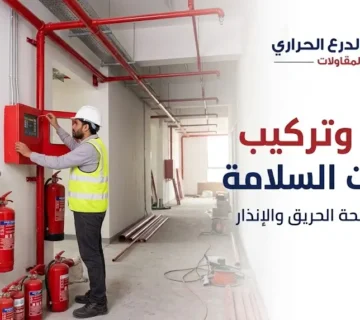

The Fire Alarm Control Panel (FACP) serves as the master controller and critical infrastructure for life safety and property protection in industrial facilities and commercial properties. Consequently, root-cause remediation for any fire alarm panel faults extends beyond simply silencing internal buzzers to precision diagnostic analysis of voltage, current, and field communication loops to ensure protection against unexpected operational vulnerabilities. This integrated engineering role is delivered by the Thermoshield platform (thermoshield.sa) per established standards and regulatory bylaws.

Table of Contents
- Executive Brief for Handling Alarm Panel Faults (BLUF)
- Operational Engineering: Root Causes of Fire Alarm Panel Faults
- Trouble Conditions Diagnosis and Reading FACP Screens
- Power and Battery Faults: AC Fail Remediation and Backup Testing
- Ground Faults: Technical Causes and Tracing Methods
- Open Circuits and Device Missing Conditions
- Nuisance False Alarms: Engineering Causes and Solutions
- Common Fire Alarm Panel Faults Diagnosis Matrix
- Integration with Industrial Gas Detectors for Explosion Prevention
- Saudi Civil Defense Requirements to Avoid Panel Faults
- Visual Inspection and Periodic Testing to Prevent Sudden Failures
- Common Technician Mistakes When Troubleshooting Alarm Panels
- Frequently Asked Questions (FAQ)
- Conclusion
Call Us |
Executive Brief for Handling Alarm Panel Faults (BLUF)
Immediate Direct Response: Dealing with trouble messages requires muting the internal buzzer via Trouble Silence, refraining entirely from pressing System Reset before logging codes shown on the LCD display, and noting the Loop ID / Zone Number and Device Address. Follow this by checking continuous reference voltage balance across loops using a multimeter to confirm no insulation breakdown to earth (< 0.1 MΩ), verifying backup battery voltage is at least 24V DC, and confirming the presence of End-of-Line Resistors matching manufacturer specifications.
Operational Engineering: Root Causes of Fire Alarm Panel Faults and Impact on Safety Readiness
Repeated operational disruptions in central alarm panels stem from high-sensitivity electronic systems interacting with harsh environmental and electrical variables, categorized into three engineering levels:
- Environmental Degradation: Exposure of surface-mount components and field detectors to extreme temperatures and humidity beyond design thresholds, accelerating insulation breakdown and dust accumulation inside optical chambers.
- Electromagnetic Interference & Power Surges (EMI): Routing signal cables alongside medium-voltage power lines or AC motors without Shielded Twisted Pair cables, generating inductive currents corrupting digital communication packets between panels and sensors.
- Chemical Aging of Power Storage: Declining electrochemical kinetics in valve-regulated lead-acid batteries (VRLA), causing increased internal resistance and reduced charge retention under full load.
Ignoring these engineering faults shifts the system from Active Surveillance to a Fail-Disabled State, depriving the building of early warning and violating mandatory fire protection requirements.
Trouble Conditions Diagnosis and Reading FACP Screens
Modern alarm panels utilize staged diagnostic logic displaying fault types via internal serial protocols. The reference matrix below illustrates how to decode system status indicators:
[System Status Matrix]
── NORMAL ────────────────────────────> Stable system, voltage and loops match
── ALARM (Red LED) ───────────────────> Actual fire detection (emergency)
── SUPERVISORY (Yellow LED) ──────────> Monitoring mechanical device (valve, pressure)
── TROUBLE / FAULT (Yellow LED) ──────> Electrotechnical fault in system
- Trouble / Fault Condition: Amber LED activation indicates an open, short, or reference voltage drop in an operational path, accompanied by a 0.5–1 Hz continuous tone.
- Zone / Loop Identification: Microprocessor identifies the faulty circuit (e.g., Loop 02 Fault or Zone 05 Open), followed by the affected device address (e.g., Dev 043 – Optical Smoke).
- Internal Hardware Diagnostics: Internal tracking messages like Internal Ram Err or Card 01 Comm Fail, reflecting lost communication with I/O cards via internal data buses.
Power and Battery Faults: AC Fail Remediation and Backup Testing
Direct Power Diagnostics: AC Fail occurs when AC input voltage drops below 85% of nominal (< 195V for 230V lines), while Battery Trouble indicates internal resistance exceeding 1.5 Ω or surface float voltage dropping below 27.1V in nominal 24V systems.
Engineering Inspection & Remediation Steps:
- Main Input & Transformer Verification: Measure AC input voltage using a multimeter, check sub-panel breakers with Lock-out/Tag-out protocols, and continuity test primary and secondary fuses.
- Backup Battery Test Protocol (SLA Batteries): Verify float voltage output stability at $27.3\text{ V DC} \pm 0.3\text{ V}$ at 25°C. Conduct conductance/load testing ensuring total voltage does not drop below $21.0\text{ V DC}$ during standby discharge (24 hours monitoring followed by 30 minutes full alarm). Confirm series wiring harness tightness ($12\text{ V} \times 2$) and clean terminals.
Call Us |
Ground Fault: Technical Causes and Tracing Methods
Mechanical Fault Nature: Ground faults represent an insulation barrier breakdown between live system conductors (positive or negative) and the building metal structure or panel chassis connected to general earth ground, leaking operational standby current.
       [Fire Alarm Control Panel FACP]
       (+) ─── V_ref ───┐
                        │ [Natural insulation resistance > 10MΩ]
       (-) ─── Return ──┼─────── (Ground)
                        │
                        ▼ (Breakdown state: R < 100kΩ)
              [Contact point with building structure]
Step-by-Step Field Tracing & Isolation Methodology:
- Initial Differential Measurement: Measure DC voltage between positive terminal and ground ($V_{+ \text{ to GND}}$) and negative terminal and ground ($V_{- \text{ to GND}}$). Normal status shows stable mid-reference voltage (1.5–2.5V). Readings near zero alongside full line voltage (~24V) on the other confirm direct contact.
- Loop/Zone Isolation: Disconnect external SLC loops and NAC circuits one by one from panel terminals, monitoring panel earth fault indicators to isolate the leaking path.
- Binary Halving Technique: Move to the midpoint of the suspicious run, disconnect cable from a detector base or isolator module, measure insulation resistance using a megohmmeter (< 50V DC test voltage to prevent component damage), and repeat until isolating damaged sections typically caused by cable insulation chafing against sharp conduit edges or moisture inside junction boxes.
Open Circuits and Device Missing Conditions
Physical Fault Concept: Open circuits result from a physical break in the signal cable pathway preventing loop continuity, whereas device missing indicates the microprocessor’s failure to retrieve a polling response from a specific digital address within allotted timeframes.
Inspection & Remediation Methods:
- Addressable SLC Circuits (Class A vs Class B): In Class B (Style 4), breaks cause downstream devices to drop, generating Missing Devices faults; location is identified by measuring line continuity resistance to estimate distance. In Class A (Style 6 & 7), loops feed from both ends, and breaks trigger Open Loop faults while maintaining device communication; tracking is performed by measuring voltage from return terminals back to adjacent interrupted detectors.
- Single Device Missing: Check mechanical detector base seating and twist-lock tightness, measure DC voltage across base terminals ($V_{\text{SLC}}$) to confirm operating voltage (16–28V), and inspect address configurations (DIP switches) to verify address matching or copper contact oxidation.
Nuisance False Alarms: Engineering Causes and Solutions
False alarms pose a severe threat to facility safety by causing psychological habituation, weakening occupant response during actual emergencies.
Common Causes: Particulate contamination of optical chambers from industrial dust and fibers, stray environmental factors like cooking vapors or heavy air currents from adjacent AC diffusers (< 1 meter), and insect ingress inside dark chamber screens.
Preventive & Remediation Solutions: Activate Alarm Verification Feature (delaying general alarms by 15–30 seconds upon initial smoke detection), deploy Multi-Criteria Detectors combining optical smoke with thermal and carbon monoxide sensors, and execute vacuum maintenance combined with Drift Compensation Analysis to replace contaminated detectors proactively.
Common Fire Alarm Panel Faults Diagnosis Matrix
| Operational Fault | LCD Screen Message | Engineering Root Cause | Inspection & Measurement Method | Engineering Corrective Action |
|---|---|---|---|---|
| AC Power Loss | AC FAIL / POWER LOSS | Sub-breaker tripped, internal transformer failure, or dropped feeder phase. | Measure input voltage with multimeter ($< 195\text{ V AC}$). | Reset breaker, replace blown fuse, inspect supply network stability. |
| Battery Trouble | BATT TROUBLE / LOW BATT | Voltage drop below $21\text{ V}$, degraded internal cells, or blown charger fuse. | Measure surface voltage, use conductance and internal resistance tester. | Replace faulty batteries with matching capacity pair (Ah), clean terminals. |
| Ground Fault | EARTH FAULT / GROUND FAULT | SLC or NAC cable contact with building structure or wet metal conduit. | Measure DC voltage differential between polarity $(+ / -)$ and earth ground. | Segment loop, trace leak point, re-insulate or replace damaged cables. |
| Open Circuit | OPEN CKT / LOOP OPEN | Physical cable cut or loose terminal screws on detector base. | Continuity and ohm resistance testing across path, verify EOL resistor. | Retighten loose wires or splice cut sections with certified cables. |
| Short Circuit | SHORT CKT / SLC SHORT | Positive-to-negative conductor contact in signal cable or damaged device insulation. | Measure resistance between positive and negative conductors ($R \approx 0\ \Omega$). | Trace isolator module activation points and isolate shorted section. |
| Device Missing | DEV MISSING / DEV COMM FAIL | Electronic failure in detector base or microprocessor address fault (DIP switch). | Measure voltage at target device base, verify digital address code. | Clean contacts, match address with panel programming, or replace field head. |
| Dirty Detector | DIRTY DETECTOR / MAINT REQ | Dust accumulation in optical chamber exceeding automatic drift compensation limit. | Review percentage dust sensitivity level via panel maintenance menu. | Remove detector, clean with filtered compressed air, or replace head. |
Integration with Industrial Gas Detectors for Explosion Prevention
In petrochemical facilities, chemical warehouses, and power plants, alarm systems remain incomplete without integrating FACPs with advanced gas detectors to form a unified early warning network preceding fire ignition; absence of integration leads to anomalous current readings generating unverified panel faults from overload.
[Gas Sensor System] ──(4-20mA / Modbus)──> [Addressable Monitor Module] ──(SLC Loop)──> [Central FACP]
Industrial Gas Detection Technologies:
- Catalytic Bead / Pellistor: Relies on catalytic combustion of hydrocarbon gases (methane, propane) via Wheatstone bridge; requires calibration against silicone poisoning.
- Point & Open-Path Infrared (PIR/NDIR & OPIR): Measures hydrocarbon gas absorption across specific infrared wavelengths; immune to chemical poisoning, covering open paths up to 120 meters.
- Tunable Diode Laser Spectroscopy (TDLS / ELDS): Highly selective detection of trace toxic/flammable gas leaks without cross-interference.
- Molecular Property Spectrometer (MPS): Modern MEMS-based technology analyzing molecular weight and thermodynamics to classify flammable gas mixtures without calibration drift.
- Ultrasonic Gas Leak Detectors (UGLD): Detects acoustic noise from high-pressure gas leaks across micro-orifices instantly without waiting for gas cloud accumulation.
Saudi Civil Defense Requirements to Avoid Fire Alarm Panel Faults
The General Directorate of Civil Defense in Saudi Arabia, per Saudi Building Code SBC 801 and NFPA standards, enforces mandatory regulations: compulsory annual maintenance contracts with licensed companies via the Salama portal, maintaining a certified Fire Logbook, direct bridging integration in vital facilities with trouble states prohibited beyond statutory windows, and banning unlisted components lacking UL, FM, or SASO compliance.
Call Us |
Visual Inspection and Periodic Testing to Prevent Sudden Failures
Preventive maintenance schedules per NFPA 72 include:
- Weekly/Monthly Inspection: Visual FACP check confirming Power On green LED and zero faults, testing indicator lamps via Lamp Test, and executing operational tests on manual call points rotationally.
- Quarterly Inspection: Check dust accumulation on detectors, inspect insulation and conduit integrity, and test network card communication.
- Semi-Annual Inspection: Emergency battery testing by dropping AC power for 2 hours, performing bump tests on gas detector sample cells using calibration gas.
- Comprehensive Annual Inspection: 100% testing of field input devices using aerosol smoke dispensers and calibrated heat sources, insulation resistance testing of SLC and NAC lines via megohmmeter above 10 MΩ, thorough cleaning and calibration of gas detectors, and waterflow switch verification.
Common Technician Mistakes When Troubleshooting Alarm Panels
Unqualified technician practices turn simple faults into complex issues:
- Direct Resistor Bridging: Installing EOL resistors directly inside the panel to silence Open Circuits instead of finding field breaks, isolating loops and leaving areas unprotected.
- Repetitive Manual Reset: Clearing fault signals repeatedly to discharge capacitors without fixing insulation breakdown, causing faults to recur.
- Mixing Communication Protocols: Using detectors with protocols mismatched to the FACP, causing polling delays and unknown device faults.
- Improper Shield Grounding: Terminating drain wires at both ends, creating ground loops that amplify electrical noise instead of grounding only at the main panel end.
Frequently Asked Questions
What is the first immediate action to take when fire alarm panel faults occur?
Press Trouble Silence to stop the buzzer, avoid pressing Reset, record circuit and device addresses from the LCD, review event history, and contact Thermoshield’s specialized engineering team (thermoshield.sa) for field support.
How do I differentiate between positive and negative ground faults?
Measure DC voltage via multimeter between circuit terminals and panel earth ground. Voltage near zero between positive and ground denotes positive ground fault (+ Earth Fault); near zero between negative and ground denotes negative ground fault (- Earth Fault).
Can fire alarm panels operate on AC power alone without emergency backup batteries?
Strictly prohibited. Panels reject normal status and trigger constant Battery Missing faults. Civil Defense and SBC 801 require batteries to ensure automatic system continuity during grid power loss.
What causes repeated failure of the internal panel battery charger?
Installing batteries with amp-hour (Ah) ratings far exceeding panel charger capacity limits, forcing power supplies to operate under peak thermal stress during long charge cycles, or unstable AC voltage without surge protection.
When do gas detector readings become a hazard requiring full facility evacuation?
When flammable gas concentrations exceed 40% of LEL in industrial sites, or when toxic gases exceed Immediately Dangerous to Life or Health (IDLH) limits specified in occupational safety standards.
Do atmospheric dust and dirt affect panel electronic circuit boards?
Yes, dust contains metallic particles and moisture-absorbing compounds, creating stray micro-conduction paths across motherboard copper traces, causing mysterious connection faults and sudden loop card failures unless IP65-rated enclosures are used.
Call Us |
Conclusion
Managing alarm and gas detection systems requires engineering precision and regulatory compliance. Technical teams at Thermoshield (thermoshield.sa) provide comprehensive solutions including calibration, digital diagnostic testing, and Civil Defense-approved periodic maintenance contracts to maintain facility safety and uninterrupted safety system efficiency.